How to Repair GOB LED Display Modules
A detailed repair guide for GOB LED display modules, covering resin evaluation, safe glue removal, dead pixel repair, LED replacement, clear resin refilling, curing, optical matching, and cases where GOB modules should not be repaired.
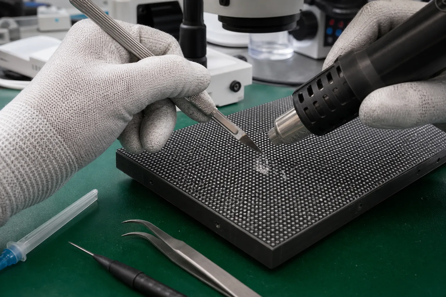
Glue-on-Board Repair
How to Repair GOB LED Display Modules
GOB modules protect LED pixels with a transparent glue or resin layer. This improves impact and moisture resistance, but it also makes pixel repair slower, riskier, and more dependent on controlled resin removal and optical restoration.
Evaluate
Confirm the resin type, damage depth, and whether the module is repairable.
Open
Remove only enough glue to expose the damaged pixel and pads.
Repair
Replace the LED or repair the local circuit with controlled heat.
Restore
Refill, cure, polish, and test optical consistency.
1. What Makes GOB Repair Different?
On standard SMD modules, the technician can access the LED package and solder pads directly. On a GOB module, the LED surface is covered by a protective transparent layer. That layer may be soft, semi-hard, or hard depending on the manufacturer and resin formula.
The repair challenge is twofold: the electrical fault must be repaired, and the optical surface must be restored so the repaired area does not appear cloudy, uneven, yellow, or brighter than surrounding pixels.
| GOB condition | Repair difficulty | Notes |
|---|---|---|
| Soft transparent glue | Moderate | Can often be removed locally with controlled tools and lower risk |
| Hard resin layer | High | Greater risk of damaging nearby LEDs, mask, and solder joints |
| Deep impact damage | High | May include broken LEDs, cracked PCB traces, and resin delamination |
| Moisture under resin | Very high | Hidden corrosion may spread; long-term reliability is uncertain |
| Large cloudy or yellowed area | Often not economical | Optical restoration may not match the original surface |
2. Diagnose Before Removing Resin
Run full red, green, blue, white, grayscale, and scan-line patterns. Determine whether the issue is a single pixel, a group of pixels, a row, a column, or a large area. A row/column fault usually belongs to the driver or scan circuit and may not require opening the front resin layer.
Inspect from several angles under strong side light. Look for bubbles, cracks, delamination, whitening, black spots, lifted resin, or impact marks around the dead pixel.
3. Tools for GOB Module Repair
- Microscope or high-resolution inspection camera
- Precision blade, micro scraper, and fine tweezers
- Temperature-controlled hot-air station with small nozzle
- Fine soldering iron, flux, solder wick, and low-temperature solder
- Compatible replacement LED with matching package, polarity, and optical bin
- Clear repair resin or manufacturer-approved glue
- UV curing lamp or curing method required by the selected resin
- Lint-free swabs, PCB cleaner, and polishing materials if appropriate
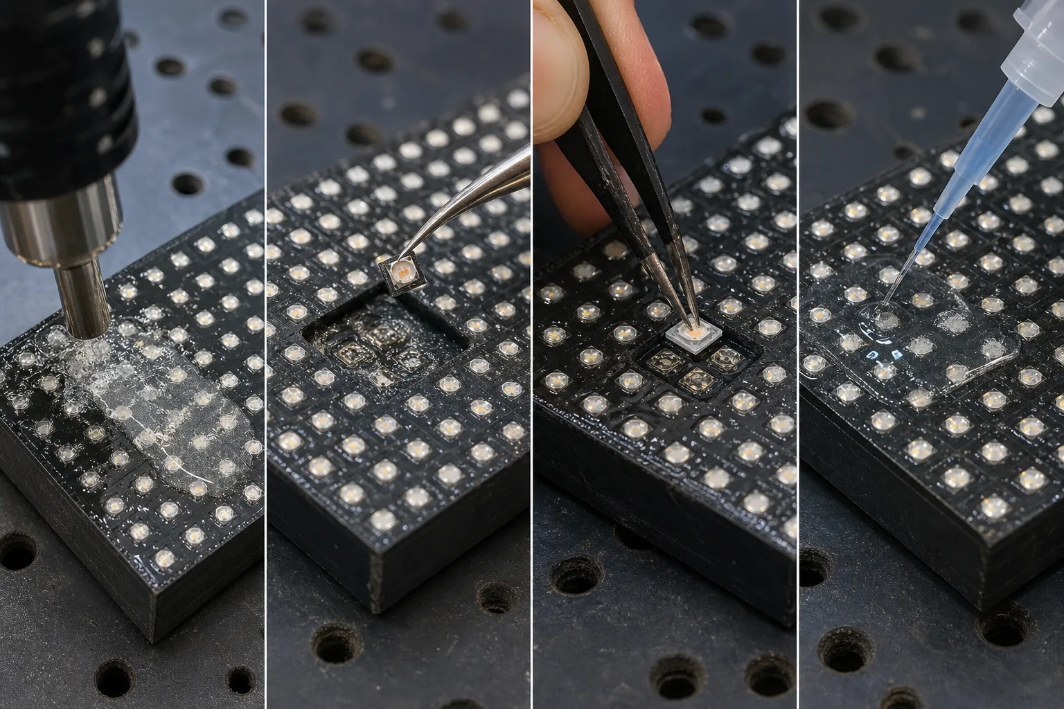
4. Local Resin Removal Workflow
- Mark the smallest repair window. The opening should expose only the target LED and a small margin.
- Test resin response carefully. Different GOB layers soften differently under heat or mechanical scraping.
- Remove resin slowly. Work in thin layers rather than trying to lift one large piece.
- Avoid cutting nearby LED bodies. Side pressure can crack adjacent packages or disturb solder joints.
- Stop when pads are accessible. Extra resin removal increases optical restoration difficulty.
Important: do not use aggressive solvents unless the module manufacturer confirms compatibility. Many solvents can whiten resin, attack LED encapsulation, or weaken the mask surface.
5. Replace the Damaged LED or Repair the Circuit
After the LED is exposed, treat the repair like a fine-pitch SMD repair but with less thermal margin. Use small tools, low airflow, and short heating time. Protect the surrounding resin because it can deform, discolor, or trap contamination.
- Photograph LED polarity before removal.
- Apply a small amount of flux only where needed.
- Remove the failed LED with controlled hot air or iron technique appropriate to the package.
- Clean pads without lifting them.
- Install the matching replacement LED and verify alignment under magnification.
- Test RGB channels before resin refill.
6. Refill and Cure the GOB Surface
The refill stage determines whether the repair is visible. Use a compatible clear resin with suitable hardness, transparency, adhesion, and curing behavior. Avoid bubbles by applying slowly and allowing the resin to settle.
Bubble control
Apply resin from one side and avoid stirring. Trapped bubbles scatter light and become obvious on white images.
Surface height
Match the surrounding resin level. A raised area changes viewing angle; a low spot collects dust and creates shadows.
Curing
Follow the resin curing method and time. Under-cured material may remain tacky; over-curing can cause haze or shrinkage.
Optical match
Check low-gray, full-white, and side-angle viewing. A repair can pass electrical testing but fail visually.
7. Final Testing Procedure
- Test red, green, blue, white, and low-gray patterns.
- Inspect the repaired pixel from front and side angles.
- Check for resin bubbles, haze, scratches, dust, and height mismatch.
- Run the module for a warm-up period and confirm the pixel remains stable.
- Verify neighboring pixels were not moved or overheated.
- For rental modules, perform gentle vibration/tap testing after curing.
8. When Not to Repair a GOB Module
Do not repair if the resin is widely delaminated, the surface is deeply cracked, moisture has spread under the coating, multiple pixels are corroded, the PCB is burned, or the customer requires a perfectly invisible repair in a high-end fine-pitch installation. In those cases, module replacement is often more reliable.
Final Thoughts
GOB LED display repair requires both electronic repair skill and surface restoration skill. The repair is successful only when the pixel works electrically and the protective surface looks optically consistent.
For service teams, the safest workflow is to diagnose first, open the smallest possible area, use compatible materials, and document the repair before reinstalling the module.