How to Identify a Bad LED Driver IC
A step-by-step diagnostic workflow for identifying a bad LED driver IC on an LED display module, including pattern testing, pin comparison, short-circuit checks, signal tracing, thermal inspection, and safe IC replacement confirmation.
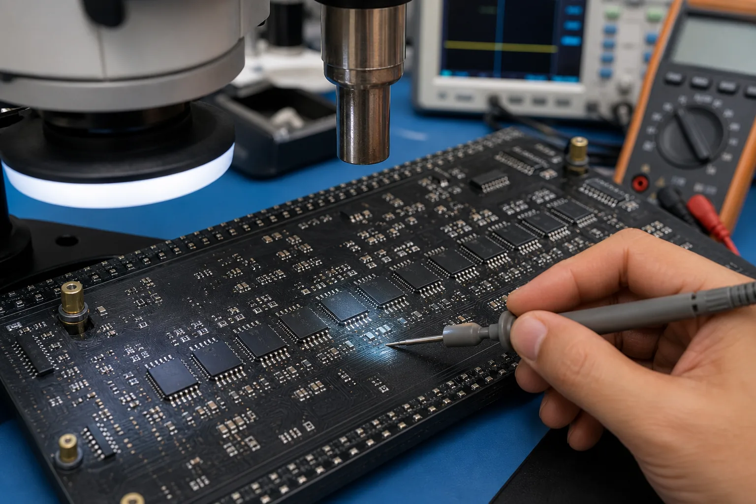
Driver IC Diagnostic Workflow
How to Identify a Bad LED Driver IC
Replacing a driver IC without proof can waste time and damage the PCB. A better workflow is to compare the suspect IC with a known-good neighbor, verify the load, check signal continuity, and only replace the chip when the evidence points to the IC itself.
1. Start With the Display Pattern
Run red, green, blue, white, grayscale, horizontal line, vertical line, and moving video test patterns. A driver IC fault usually produces a repeatable physical pattern. If the symptom changes with the source, cable, receiving-card port, or software mapping, diagnose those areas first.
| Pattern result | What it suggests | Next check |
|---|---|---|
| One fixed vertical group fails | Output channel, trace, or LED load problem | Compare output pins and load resistance |
| Downstream ICs fail after one chip | Data cascade interruption | Check data input/output around the suspect IC |
| One color missing only in a fixed area | Color-specific output bank issue | Trace the RGB channel path and compare with a good bank |
| Fault disappears when pressing PCB | Cold solder joint or cracked trace | Inspect pins, vias, and solder joints before replacing IC |
| IC overheats quickly | Shorted IC or shorted output load | Power off and check resistance to ground |
2. Locate the Suspect IC
Use the module layout to map the visible bad area to the driver IC section. On many modules, driver ICs are arranged in repeated blocks. Use a good module or a neighboring circuit as a reference and follow the trace direction from the failed pixel group back to the IC outputs.
3. Check for External Shorts First
Before blaming the IC, power off the module and check for shorts on the LED load side. A shorted LED bead, solder bridge, water corrosion, damaged pad, or copper debris can overload a good IC and make it hot. Replacing the chip without clearing the short can immediately damage the new IC.
Resistance comparison
Compare the suspect output-to-ground reading with identical outputs on nearby good ICs.
Solder inspection
Check for bridges between IC pins, LED pads, vias, and nearby passive components.
Moisture corrosion
Corrosion can create leakage paths that appear only under power or humidity.
LED load isolation
If possible, isolate or remove the shorted load before deciding the IC is bad.
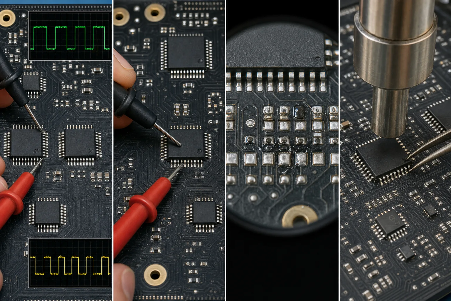
4. Compare Power and Signals
With the module powered safely, compare VCC, ground, data, clock, latch, and output-enable behavior between the suspect IC and a good IC. If the suspect IC has missing input signals, the problem may be upstream. If inputs are normal but outputs are abnormal, the IC becomes a stronger suspect.
| Check point | Healthy indication | Bad indication |
|---|---|---|
| VCC pin | Stable supply under load | Low, missing, noisy, or dropping when pattern changes |
| GND pin | Low resistance and clean reference | Cracked ground via or unstable reference |
| Data input | Comparable activity to previous stage | No signal before the IC means upstream fault |
| Data output | Data continues to the next IC | Input present but output missing suggests cascade failure |
| Output channel | Comparable waveform/resistance to good channels | Stuck low, stuck high, open, shorted, or abnormal leakage |
5. Use Thermal Clues Carefully
Thermal inspection is helpful but not final proof. A hot IC may be internally shorted, or it may be driving an external short. A cool IC may be dead because it has no power or no input signal. Always combine temperature with electrical checks.
6. When Replacement Is Justified
Replace the driver IC when the fault pattern maps to that IC, external LED/load shorts have been excluded, supply and input signals are present, outputs are abnormal compared with a good IC, and the same problem remains after inspecting solder joints and traces.
- Record the IC model, pin-1 orientation, and surrounding component layout.
- Protect nearby LEDs, connectors, and plastic parts from heat.
- Remove the suspect IC with controlled hot air and minimum mechanical force.
- Clean pads and inspect for lifted pads or solder bridges.
- Install the same IC model or confirmed compatible replacement.
- Test low-current first if possible, then run full RGB and grayscale patterns.
7. Post-Replacement Verification
- The original pattern defect is gone.
- No new lines, flicker, ghosting, or color loss appears.
- IC temperature is similar to neighboring chips during the same pattern.
- Low-gray patterns are stable and free of leakage artifacts.
- Moving video and scan-line patterns remain stable after warm-up.
- The repaired area is cleaned and inspected under magnification.
Final Thoughts
A bad LED driver IC is identified by evidence, not guesswork. The strongest diagnosis comes from matching the visible failure area to the IC, excluding external shorts, comparing signals with a good circuit, and confirming abnormal output behavior.
This approach reduces unnecessary IC replacement, protects fragile LED module PCBs, and improves repair reliability for fine-pitch and rental LED display modules.